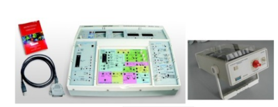
Position Control & DC Servo Control System Trainer Setup
Trainer consist of Master Unit, Experiment Panel & Interfacing Module:
Master unit –
Built in power supply:DC supply +12V,500mA. 1phase sine reference for cosine firing 30Vpp max. 17Vdc, 500mA unregulated for driving pulse, Variable DC power supply : 7 to 14V/3A
Display: a) DPM – 2Nos. i) For Temp. upto 1000C & intensity in Lux (2000) ii) For speed 2000 rpm & voltage upto 20V., b) Analog Meter – 2Nos. i) Centre zero for display of process error (+9V) ii) For MV/SP (0-2.5V)
Operating voltage: Switch selectable 220-240Vac, ±10%, 50Hz, 75VA
Online monitoring / Data acquisition / PID Software: on Installable (CD) works under XP, WIN7/8/10 PC with parallel port / USB needed.
Operating modes: a) Simulator Mode – Tests data already stored in files (*.txt) & Drawing graph for all P,PI,PD & PID modes.
b) Process Monitoring Mode – Drawing graphs of analog data presented at CH 0 & CH of Computer Interface. Cursors for X & Y axis for measurement & online graphs savings for reproduction
c) PID controller Mode – PID controller with parameters like Integral Time Ti (0.01-64000), Sampling Time Ts (0.1- 99.9), Derivative Time Td (0.1-99.9), Proportional Band Pb(1-999), Derivative Gain Kd(1-999), Set Value Rn (0- 99.9), PID output Upper Limit Uh(0-99.9), PID output Lower Limit Ul (0- 99.9). Facility to set units for output viz. Percentage (%), oC, RPM, Voltage(V), mm, LPH, kg/cm2, si/cm, degree. Supports experiments with advance process control scheme viz; Ratio, Cascade, feed forward with user selectable Aux PID, Ratio station & programmable FF transfer function calculator, selective and split control strategies, Multi DPM Screen.
Computer Interface Adapter:Optoisolated Adaptor to prevent damage to PC parallel port (25 pin LPT) due to wrong connections. Interfaces through 25 pin M to F cable 1mtr Length. PC/WINXP/7/8/10 not in scope of supply. 4 ADC channels : 0 to 2.5V full scale. 1 DAC channel : O/P 2.5 V FS. V to I Function block : Input : 0-2.5Vdc;O/p: 0-20 or 4-20mA, in 100E load Max; USB IO module to interface 25 pin D connector on CIA panel to USB PC port enclosed in 25 Pin D shell using Type A to mini B cable. V to PWM function block : I/P -0-2.5V, O/P-1KHz PWM O/P ±9V.
Controller selection P,PI,PD,PID with slide switch
Parameter settings : Integral Time Ti (0.5-25Sec) : Derivative Time Td (0-2Sec) : Proportional Band Pb (5- 200%) : Set point (-9V- +9V)
Operating modes : Fast (X 100/10mSec) for oscilloscope, Slow ( X 0.1/1Sec) for PC interface. 2 No. Level shifter converting process O/p (+9V) to 0-2.5V for PC interface & Actuator panel. Test points for Process Error, Set Point (Rn), Measured Value (Cn), Controller output (Un).
Built in function generator: O/p waveform selectable sine, triangular & square. O/p freq. range from 0.016Hz to 166Hz, 4 steps & fine control pot. Variable amplitude control 0 to +9V
Experimentation Panel Specifications: Servo interface unit – Control Interface circuit for AC & DC servo motor, signal conditioning circuit for speed sensor to O/P 0 – 2.5VDC (2500RPM) with speed direction. Level shifter 0 – 2.5V to ± 9V (2nos). Relay control characteristics : Hystersis, Dead band & Relay control circuit (2term & 3 term), process block for 2Nos. of 1st order lag / integral + transport lag, error and gain block for process simulation. Phase plane analysis by display of X & X dot.
DC Servo Position Control Panel specification – PMDC Motor 12V DC, 40-Watt ND RPM 2000 RPM with gear box (Ratio 30 :1), Loading: Using PMDC Motor @ 12V/5A max. Servo Amplifer with built in 12V/3A power supply, Sensor : Photo reflective speed sensor with direction detect using 2 pairs of photo emitter detector giving Quadrature o/p’s
Reconfigurable Interface and Control Module: It is an embedded hardware device designed specifically to help students design real, complex engineering systems more quickly and affordably than ever before.
- Affordable tool to teach and implement multiple design concepts with one device
- 10 analog inputs, 6 analog outputs, 40 digital I/O lines
- Wireless, LEDs, push button, accelerometer onboard
- Xilinx FPGA and dual-core ARM Cortex-A9 processor
- Programmable with LabVIEW or C; adaptable for different programming levels
Experiments:
- Position Control System
- DC Servo Control


Reviews
There are no reviews yet.